How to Assemble a Modular Spreader Beam
Step-by-step instructions for safe assembly, configuration and rigging of modular spreader beam systems.
How do you assemble a modular spreader beam?
Knowing how to assemble a spreader beam correctly is essential for safe lifting operations. This guide explains how to assemble a modular spreader beam system step by step.
Assembly Steps
Correct assembly of a modular spreader beam is essential to ensure safe lifting operations, maintain rated capacity, and prevent structural or rigging failure.
This guide outlines the correct procedure for assembling a modular spreader beam system in accordance with manufacturer recommendations and best practice lifting standards.
Beam Assembly (Flange Connection)
The beam sections are connected using bolted flange joints. Correct alignment and bolt installation are essential to maintain structural integrity and rated capacity.
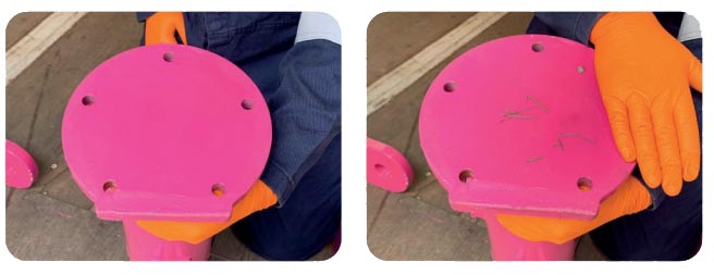
Inspect Flange Faces
Ensure all flange faces are clean and free from debris, contamination or damage before assembly begins.
Align Bolt Holes
Position the beam sections together and align the flange faces and bolt holes correctly before inserting bolts.
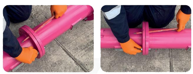
Install Bolts
Insert all supplied bolts once alignment has been achieved. Ensure correct positioning and full engagement.
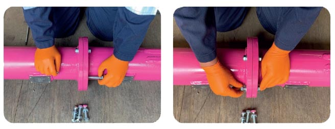
All flange bolts must be installed and tightened in accordance with the manufacturer's specified torque values before the beam is placed into service.
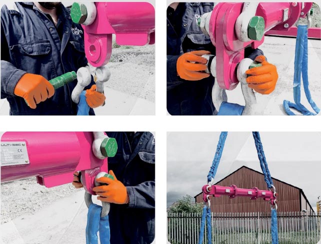
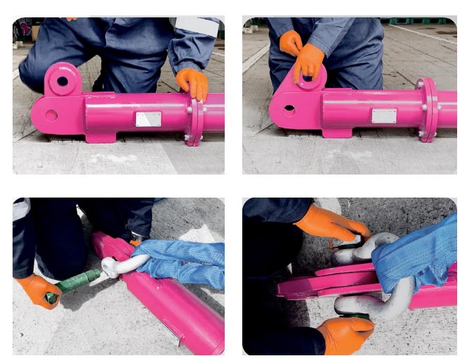
Attach Top Shackles and Slings
Attach the lifting slings to the top shackles.
- Position drop links into the lifting lug clevis
- Align clevis and lug holes correctly
- Insert shackle pin through aligned holes
- Secure using shackle nut and safety pin
Ensure all connections are correctly seated and fully secured before lifting.
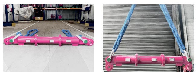
Raise the Beam
Lift the assembled beam using a suitable lifting device and ensure the lift remains controlled and stable throughout the operation.
- Attach the top rigging arrangement
- Raise the beam clear of the ground
- Confirm the beam is level and stable
- Connect the lower rigging arrangement
- Verify all connections before proceeding
The beam should remain stable and properly supported during rigging. Avoid shock loading or sudden movements.
Attach Lower Rigging
Connect the lower rigging to the beam once the assembled system has been raised and is stable.
- Connect rigging to the lower shackles
- Fit shackles into the lower hole of the drop link
- Confirm all shackle pins are correctly secured
- Drop links must remain vertical
- Lower sling angle must not exceed 6°
- Top sling angle must not exceed 45° to the vertical
Exceeding these limits can reduce lifting capacity and introduce unsafe loading conditions.